McElroy fusion equipment covers pipe sizes from ½” to 78” in diameter and offers machines to fuse individual ranges of pipe across that entire range. Choosing a fusion machine might seem simple enough: find the pipe range, and then find a machine that can fuse within that range. But just like no single machine can handle ½”-78”, there are also choices for which machine should be used based on the pipe OD, wall thickness and fusion standard required.
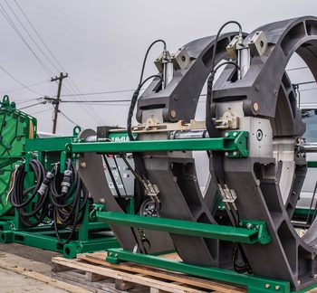
Our traditional hydraulic fusion machines are offered with high force cylinders (green), medium force cylinders (orange) and low force cylinders (yellow).
How and when to choose the size of machine and specific cylinder size is critical to supporting the fusions to be done and ensuring a good customer experience.
What is cylinder force, and why is it important?
Each cylinder and machine combination has different capabilities in terms of the size range and wall thicknesses that are best fused in that machine. Depending on factors like wall thickness and the standard being used for fusion, you may need to consider an alternative machine for yourself or your rental customers.
By making sure each customer has the right machine before they reach the jobsite, you can help ensure a positive experience for customers, along with many man-hours saved in terms of exchanging equipment.
How to determine which cylinder force meets your needs or your customers’ needs
You may have seen the image below online or in one of McElroy’s product catalogs. There is a chart for every size range of hydraulic equipment. This chart is an invaluable tool when it comes to determining which machine – and which cylinder force – is going to give you or your customers the best results when on the jobsite.
You can use this chart to guide you through the process of choosing the right machine and cylinder force. The chart itself is a step-by-step process that walks you through determining the right machine and cylinder choice for the pipe to be fused. In this case, we are going to use 6” IPS DR 11 pipe with a 412 chart.
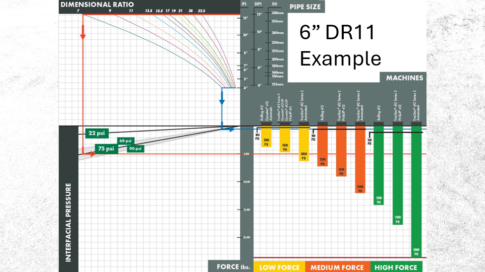
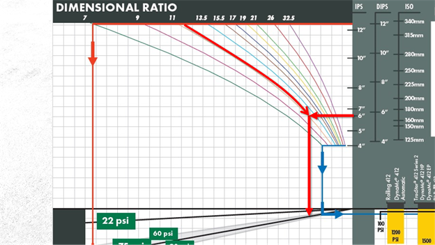
To begin, find the pipe size that corresponds to your pipe size and draw a horizontal line to the left to intersect with the sloped line designating the dimensional ratio (DR) of the pipe being used. In this example chart, the red arrows indicate that we’re using 6” IPS DR11 pipe. Next, you will draw a line vertically down from that intersection to the recommended interfacial pressure (in this case, 60-90 psi). Lastly, you will draw a line horizontally to the right across the machines listed.
NOTE: Each of these charts has a marking at 100psi. This is to note what should be considered the low end of readability on an analog machine pressure gauge. This lower pressure can also result in slower open/close times. It is suggested that you choose a machine based on pipe size that would put your machine pressure gauge reading above 100 psi. Low end pressures in this range can also be better discerned by using a DataLogger®.
The graph shown does not include drag force and should be added to the value for this chart. Alternatively, you can use McCalc® to calculate the machine pressure required for a fusion and draw that line on the chart.
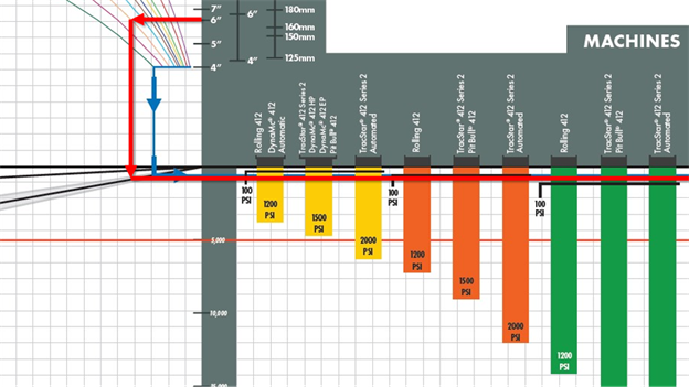
Continuing with this example, low force (yellow) and medium force (orange) machines both exceed the minimum 100 psi indicator. The high force (green) machines are very near the 100 psi mark and would be greater than 100psi when any drag amount is included. The length of the bar below the red mark also indicates how much hydraulic pressure the machine is able to exert over and above the interfacial pressure to overcome drag.
To put that into real-world terms, let’s pretend you’re planning to rent a Rolling 412 with a high-force cylinder to a company that needs to fuse 6” DR11 pipe. Let’s also assume that the job is going to include 4” DR11 fusions. While that particular machine might fuse pipe that falls within the 4” to 12” range, its cylinder force falls very near the 100 psi indicator for the 6” pipe before drag is applied. For the 4” pipe the fusion force would be 33psi – well below the capability of the high force rolling 412.
Looking closer, a low- or medium-force Rolling 412 would be a better option, or perhaps a 28 machine would be the better fit for this customer.
It sounds like a lot to remember, but keep in mind that a customer’s experience plays a tremendous part in their overall opinion. The right machine can mean the difference between a repeat customer and hours of time wasted both for you and the user in the field.
In the end, you need to understand your customer’s needs and application.
Choose the right machine(s) for the job and application taking into account:
- Pipe size
- Pipe wall thickness
- Max Fusion pressure of the machine
Use the resources available, and reach out to McElroy if you have any questions.