Measure drag pressure manually on TracStar® iSeries machines
The ability to manually measure drag on TracStar iSeries machines is available now. Introduced in the April 2022 software update (DataLogger® version 119, 1.26 and Carriage Control Module version 1.033) the new option can add functionality at all FusionGuide™ levels once enabled.
Measuring drag manually is most effective for dynamic drag scenarios such as:
- Situations in which the location along the guide rods is critical for proper drag measurement. The manual drag feature allows the user to control the position at which drag is measured.
- Jobsites on terrain that is uneven or has extreme inclines/bends.
Enable Manual Drag
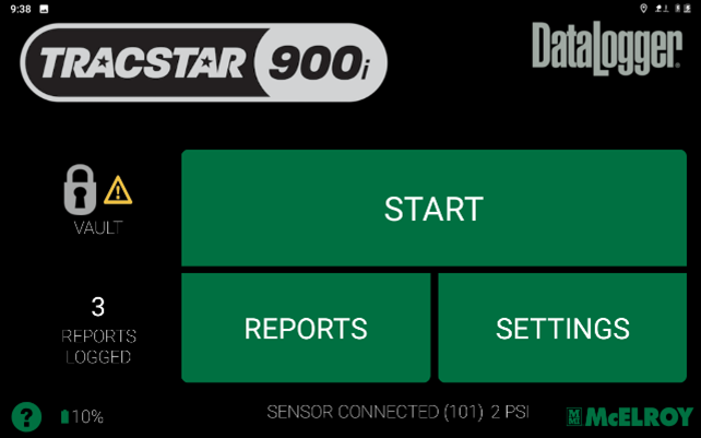
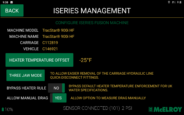
- From the Start menu on the DataLogger app tap the TracStar iSeries logo in the upper left-hand corner (Fig. 1) to access the “iSeries Management” menu (Fig. 2)
- From the “iSeries Management Menu” (Fig. 2), tap “YES” on “Allow Manual Drag” to enable the manual drag process setting
Measure Drag
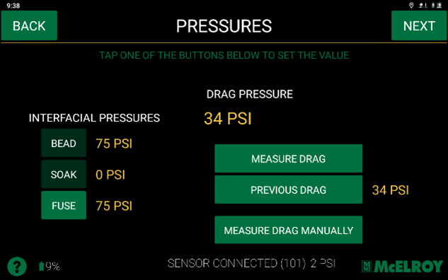
- Follow the guided workflow on the DataLogger to log a joint. Once the “Pressures” menu appears (Fig. 3) press the “Measure Drag Manually” button.
- Move the carriage to the desired position to measure drag. Typically, 1.5“ to 2” from the pipe ends.
- Tap the “Measure Drag Manually” button (Fig. 3)
- On the “Manual Drag” screen (Fig 4), the carriage position as reported by the carriage linear transducer is reported on the far left. This gives the operator an improved view to observe carriage movement beyond a visual indication. The dial in the middle and set of up/down arrow buttons on the right control the power. Power can be increased by dragging the slider on the dial clockwise or by using the up/down arrow buttons.
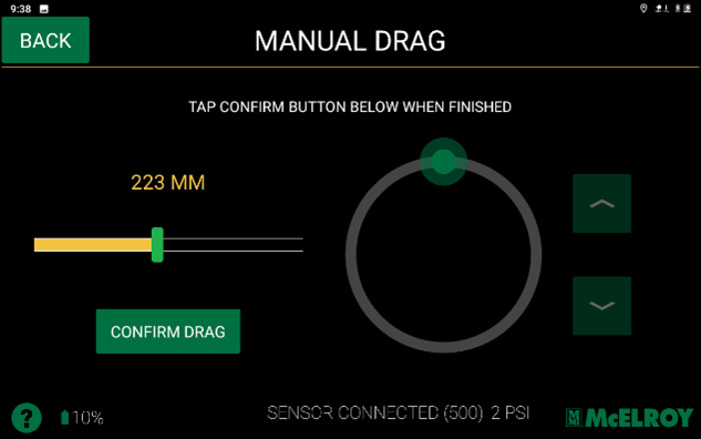
- To enable the dial on this screen the carriage position lever must be set to the closed position. The up/down arrow buttons will light up as a confirmation. (Fig. 5)
- Once the carriage position lever is locked in the closed position the operator can increase power until movement is observed.
- When the desired drag is reached as determined by the operator, return the lever to the center position. Drag has not been calculated at this point. An automatic process must run to determine the actual drag pressure, meet point, slip check, and fusion pressure values. When the lever is returned to center a “Confirm Drag” button will be enabled. (Fig. 6)
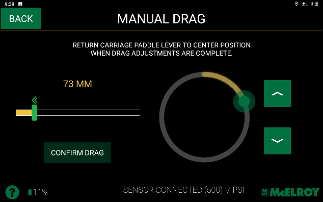
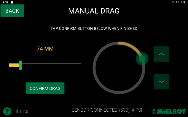
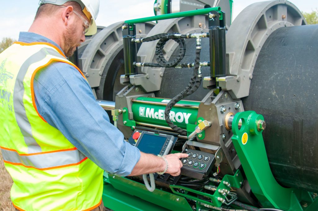
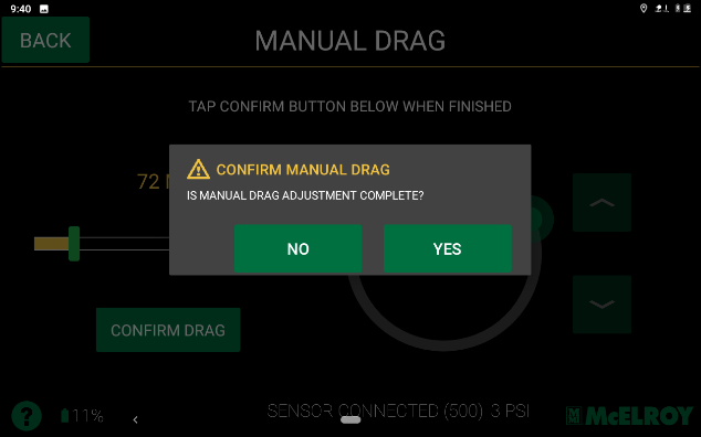
- Select the “Confirm Drag” button (Fig. 6) to begin the automatic portion of the process. Once “Confirm Drag” is selected the operator will need to confirm the manual drag measurement is complete on the DataLogger, then confirm the automatic movement by pressing the confirmation button on the keypad (Fig. 7-8).
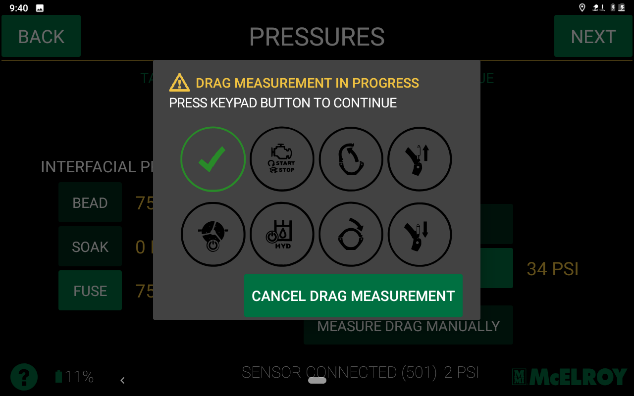
- The auto process will now begin.
- Once complete the user will be taken to the main drag measurement screen and the measured drag pressure will be presented to the user.
- The operator can now proceed with the fusion process.
For more assistance, contact McElroy Technical Support
(918) 831-9224
techsupport@mcelroy.com